Parallel projections.These “views” of the three-dimensional architectural object are parallel orthographic projections, in fact 2-dimensional representations, so that the “reading” of object positions and dimensions is unique and consistent with the medium (video or paper).
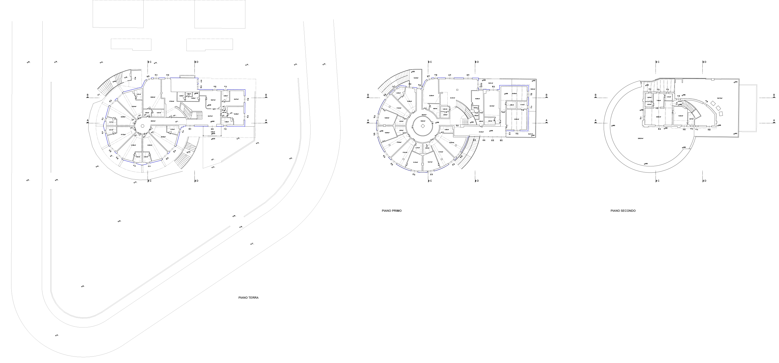
Floor plan.
In the technical drawing of architecture, floor plans are the most information-rich representations. The design itself is normally developed by starting with floor plans and then adding depth upward: this involves a strong symbolic level in the design of the plan. Technically, the plan is a horizontal, downward-looking asection about 1 meter above the main floor level (to intercept most openings: doors and windows), but it often does not correspond to a geometrically perfect section. The goal is to include as much “three-dimensional” information as possible, including elements behind the plane of view (above the plane of section) drawn as projections. Numerical textual information relating to spaces, facilities, heights, etc., is also often added to the plan.
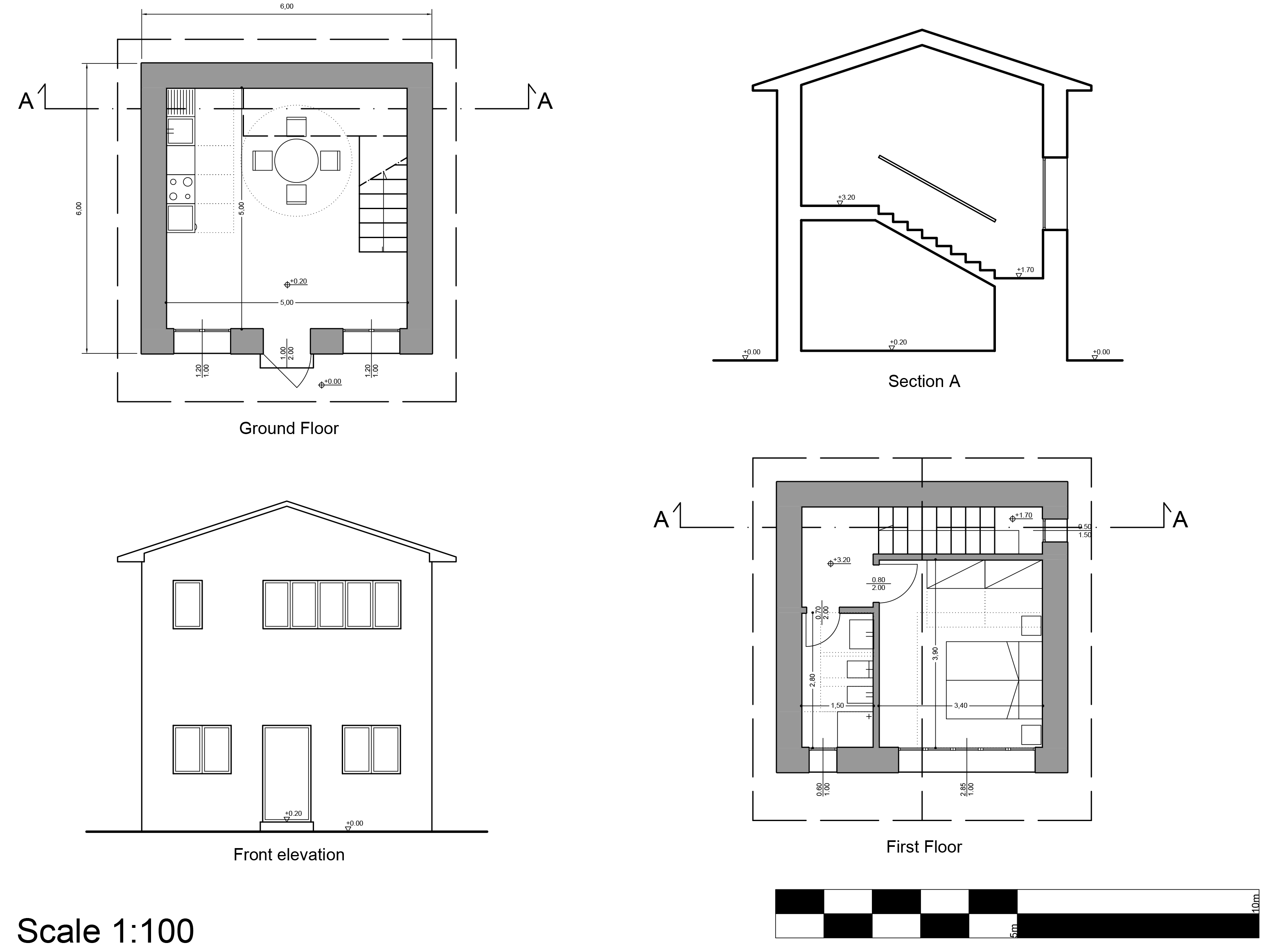
Elevation.
The elevation is typically a horizontal view of the external appearance of the architectural object. Technically, the elevation is also a vertical section but the sectioned portion is typically limited the ground. The symbolic level of elevations is rather limited to screens, openings, elevations, textual indications.

Section
The vertical section is a mixture of technical drawing of the “sectioned” part and the “elevation” part of the architectural object in view. Considering that the section plane intersects solid objects the sectioned edges are always unique continuous and closed silhouettes, except of course the ground below. When the scale of representation is reduced to enlarge the details it is possible to distinguish different objects or materials within the single sectioned edge but always with closed continuous silhouettes.
It is always absolutely necessary to indicate in all relevant plans the position of the section planes and the direction of the view by means of a line, usually line point, an arrow symbol, and the code of the referenced section.

Texts, in a board, always have only two reading directions: horizontal (looking at the board from below) and vertical (looking at the board from the left side). The need to “turn” around the board to read the texts should be avoided.

Dimensions are the symbolic elements inserted in 2D representations to indicate dimensions, positions or spaces. Linear dimensions outside objects are suitable for indicating general dimensions. Internal linear dimensions indicate internal dimensions of spaces (rooms, corridors, stairs, etc...).
The typical symbol for quoting the size of openings is formed by a line median to the opening, perpendicular to the hole, with the two dimensions of the hole: above the width, below the height.
In elevations and sections, the symbol for indicating the elevation of a point is typically a triangle with the elevation next to it (the point on the dimensioned drawing is the bottom point of the triangle)
In plans, the elevation of a point (e.g., the floor) is typically a circle superimposed with a cross and the elevation next to it (the point on the dimensioned drawing is the center of the circle).

Walls, in plan and section (if intersected by the plane) always represent “solid” objects, so they will have thick, continuous edge lines, often reimposed with a 45° or continuous color screen.
With reference to the scale of representation, the level of detail of openings changes considerably, typically:
drawing scale 1:200 = Semplici spigoli di apertura
drawing scale 1:100 = Schematic indication of opening position and overall dimensions
drawing scale 1:50 = Schematic drawing of frames and shading systems
drawing scale 1:20 = Specific drawing of frame templates and hardware.
To represent the openings, an abacus of fixtures is also used, especially at the advanced design stage: a mixed drawing/list representation that collects only the information needed to manage the locking systems

The representation of stairs in the plan is highly symbolic. Imagining the horizontal section of the plan at about 1 meter in height only the initial part of the staircase will be in view (thus drawn in a continuous line). The rest can be ignored or represented with dashed lines in projection to indicate the invisible obstructions because they are above the section. A thick inclined line is used to indicate the graphical (but not structural) break in the staircase. Obviously the floors above the ramps below see every element of the staircase is not hidden by other elements.
In the plan, the direction of ascent should be indicated for each ramp system with an arrow in the center of the ramp, with the arrow pointing in the direction in which the staircase ascends.

In the section, if a ramp is sectioned, it will be drawn exactly like any other element by limiting the details appropriately to the scale of representation.

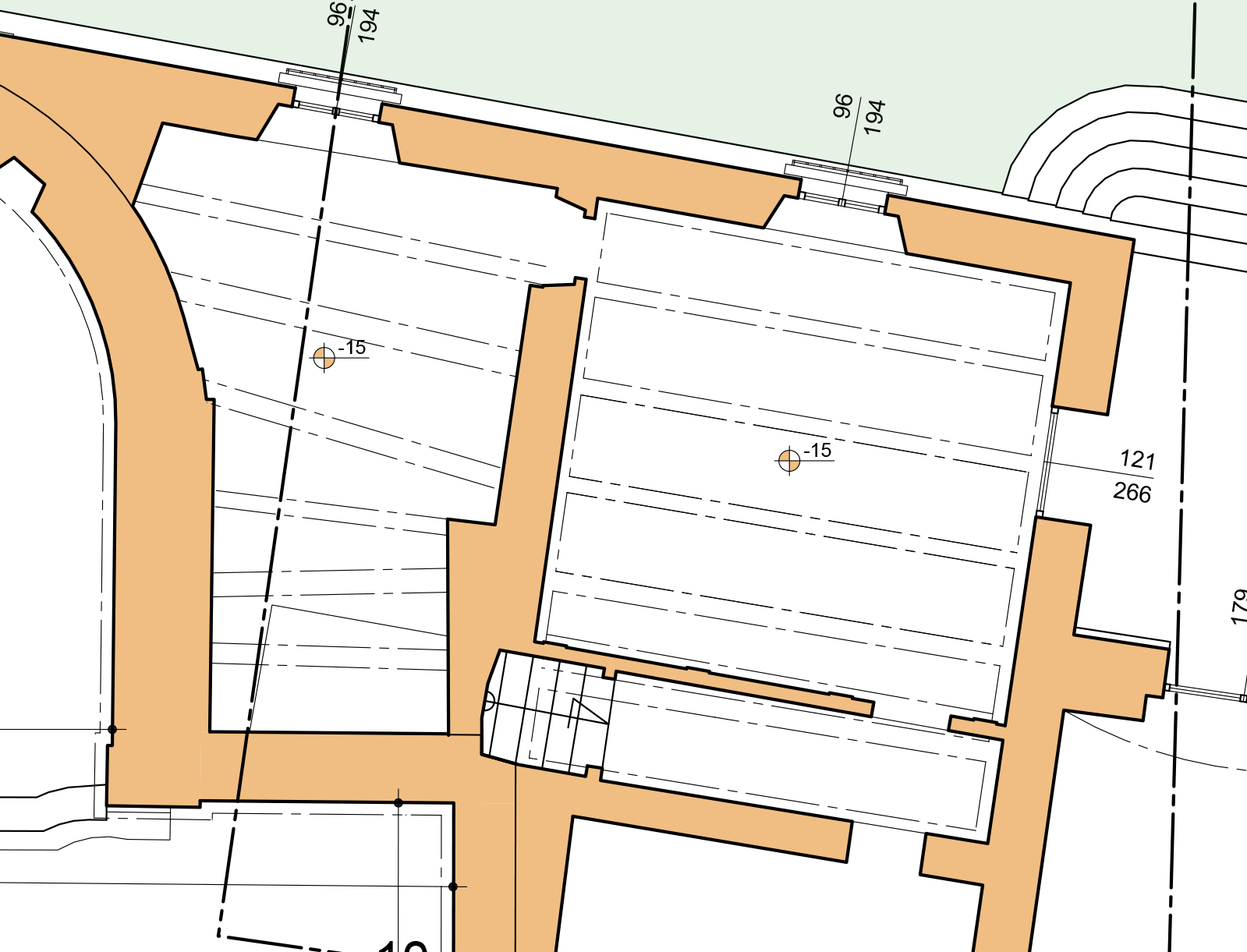
Roofs in plan are represented by:
displuvial and compluvial lines
Lines (or line screen) with orientation parallel to the maximum slope for each pitch
dashed line of the projection of the maximum overhang if the roof is above the section plane.

On the plan, it is important to indicate whether the ceiling, above the section plane, follows geometrically or contains elements that may vary the clear height above the floor level (beams, trusses, chains, compluves, etc...) by means of dashed projection lines for significant edges, and possibly textual and elevation indications.
Bathrooms and kitchens are design spaces that simultaneously involve several design disciplines (the architectural composition, water supply/drainage system, electrical, heating, smokes) so it is very useful to indicate the location of the main functional elements through symbols that schematically represent their overall dimensions, the respect spaces necessary for their use, and their type.

Vaults are special geometries with shapes that are often unreadable from simple drawing in plan on elevation/section. Since the edges fundamental to a reading of the vault typology are often not there or are not “readable” when drawn in projection in their actual position, they are reported symbolically with dotted strokes for immediate and instinctive understanding.

For terrain, which typically follows geometric variations exclusively in elevation, a system of horizontally spaced section planes is often adopted: the intersecting lines are called contour lines or isohypses. By drawing all contour lines on the plan, adding the elevation of the main ones, it is easy to interpret the elevation trend of the terrain: all points near the same curve have the same elevation; if the curves are very close together, the change in elevation is very rapid.